
The display has access to all relevant vehicle data, so why not control specific things such as “Boost Control”?With the new firmware version v3.0c, the licensed
Boost Control feature is now available for all
MFD28s, which also Works with all vehicle-specific variants. Various functions such as speed, gear and speed-dependent boost pressure control can be used. But “fail-safe” functions with exhaust gas temperature, lambda value, intake temperature and excessive boost pressure are also possible. There are also two “scramble boost” Values.Activation takes place via
License. In addition, a small amount of additional hardware is required for operation, where the boost pressure control valve is connected. If you don’t have a boost pressure sensor yet, you can order the license in a package with a 4.5 bar boost pressure sensor.
* Additional license, boost pressure sensor and at least firmware version v3.0c required, boost pressure control valve not included . Of course, you can’t just control one boost pressure control valve. Other options are:
PWM
- Water-methanol pumps
- Radiator fan
digital (on/off)
- Fan
- Second fuel pump
- Shift light LED
- Etc.
2x Scramble Boost
Two scramble boost values with fixed switching and can only be activated with a tap of the finger
5x Safety Duty
5 freely selectable values with 11 support points to correct the boost pressure
4x analog inputs
The 4 analog inputs of the display can be used for various sensors: boost pressure, exhaust gas temperature, lambda, fuel pressure
Boost pressure control valve
The activation (in Hertz) and inversion of the boost pressure control valve is precisely defined on the display
Integrated 4.5bar boost pressure sensor
Optionally, we deliver the AddOn with a 4.5 bar boost pressure sensor, which occupies one of the analog inputs of the display
Log function
The internal log function of the display enables permanent recording to the internal SD card and later evaluation on the PC/laptop
Speed basic characteristic
With 11 reference points, you first determine the basic characteristic curve of how much the valve is activated at the respective speed.
OBD2 functionality
The displays support OBD2 via Can Bus (from approx. Bj 2007) and thus have access to a lot of engine data (speed, water temperature, lambda, and many more)
Additional switching output
Another output is activated, which switches a 12V HIGH signal when a freely selectable sensor is exceeded.
OEM CAN protocol
Due to the high integrity of the displays, it is also possible to integrate them into the original Can Bus and access values - for example BMW, Audi, VW, Subaru, etc
Warnings
It is possible to create an individual warning threshold for each sensor/input and to be warned by a LARGE popup
Gear calculation / Boost by Gear
The display calculates the current gear for “Boost by Gear” from engine speed and speed
– Boost Control Settings –
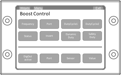
Upper area – boost pressure control
Frequency:
Frequency of the wastegate (or the corresponding controlled hardware) in Hertz ( ATTENTION: after this setting you can no longer dim the display!)
Port:
the output pin on the display that should be used for PWM (only RX or TX support PWM, others only digital (ON/OFF)) – after the port change, the display must be restarted.
DutyCycle1/2: PWM
Starting in percent. These are two fixed, switchable levels that can then be activated via widgets in the display. (Scramble Boost)
Status:
active or deactivated Boost Control or switches from “Dynamic Duty” to “Closed Loop (PID)” (available from 3.2 PID control)
inverse:
some boost pressure control valves must be addressed inversely (100%=0%). Please test the correct value here. At 100% you can no longer “blow through”.
DynamicDutyClosed Loop (PID):
Dynamic control (see below)
SafetyDuty:
takes back the control for five freely selectable values as a percentage. Eg exhaust gas temperature, intake air temperature or gear-dependent.
Lower area – additional output
DigOut:
Switch digital output active/inactive
Port:
the pin to be used for the digital output
Sensor:
Sensor that activates the output when exceeded
Value:
the value of the sensor that must be exceeded.
– Dynamic Duty Cycle –

In the Dynamic Duty Cycle area you can set the activation of the wastegate depending on the speed (in the menu under “TRI File” => “SensorInit” “RPM” must be selected appropriately).
If you now tap on the line, you can move the first point vertically by tapping again. Fine adjustment is done using the up/down arrows in the right area. The “Next arrow” takes you to the next point.
The scaling determines the sensor settings of the speed. (Menu => “Sensors” => “RPM”. Here “MinWarnVal” and “MaxWarnVal” must be assigned appropriately. In the picture “MinWarnVal” is set to 0 and “MaxWarnVal” is set to 7500 .
– Safety Duty Cycle –

You can use the Safety Duty Cycle function to correct the timing specified under “Dynamic Duty Cycle” as a percentage. So 100% corresponds to 0% activation and 0% corresponds to the value from “Dynamic Duty Cycle”.
This allows you to use safety functions such as exhaust gas temperature, but also for optimized slip (gear-dependent), as well as a step rotary switch via an analog input.
Calculation: Final starting = DynamicDutyCycle * (SafetyDuty1/100) * (SafetyDuty2/100) * (SafetyDuty3/100) * (SafetyDuty4/100) * (SafetyDuty5/100)
– Connection additional hardware –

12V (A1)
Power supply 12V, to the same power supply as the display (pin A4 on the display)
OUTA (A4) and OUTB (A2)
Output to clock valve or hardware to be controlled (12V)
ground (A3)
Connect ground to the same ground as display (A8) and ground for hardware to be controlled
INA (A8) and INB (A7)
to the display on output pin (RX, TX for PWM or RX2, TX2)
5V (A6)
Power supply for MAP sensor from display 5V
MAP (A5)
Output MAP sensor to display (one of AIN1-4)

For boost control, the wastegate is connected to the charge pressure line between the intake manifold and the wastegate.
The 12V supply to the valve comes from the addon (OUTA) and the ground to the same ground as the boost addon (pin A3).