We have updated the Ecumaster Connection Guide . It is now possible to send all 4 analog inputs of the display to the control unit.
We have also completed the document to include the serial connection. We offer a plug and play solution for this with a suitable cable between the control unit and our serial adapter.
Our MFD15 injection mold was used for the first time on January 14th, 2020!First sampling of the tool for our
MFD15 at befi-Plastic.As expected, the first parts arrived after a short time and the tool worked as planned.We’re going to adjust 1-2 little things and then we’ll produce. Many thanks to the befi-plastic team for the quick processing and help. After the change, we can finally deliver in larger quantities and our 3D printer can do other things.
We talked to Tractive Suspension at a trade fair because they were looking for a specific display for their suspension application. We found the topic extremely interesting and after the first discussions, the partnership and the associated product idea were formed.
It was supposed to be our MFD28 , but with the specification of an external control button. Since our products are designed to be flexible, even this could be implemented. Everything else can be found in the following video. At 1:24 our products appear.
A really great solution, we think, and we look forward to expanding the partnership.
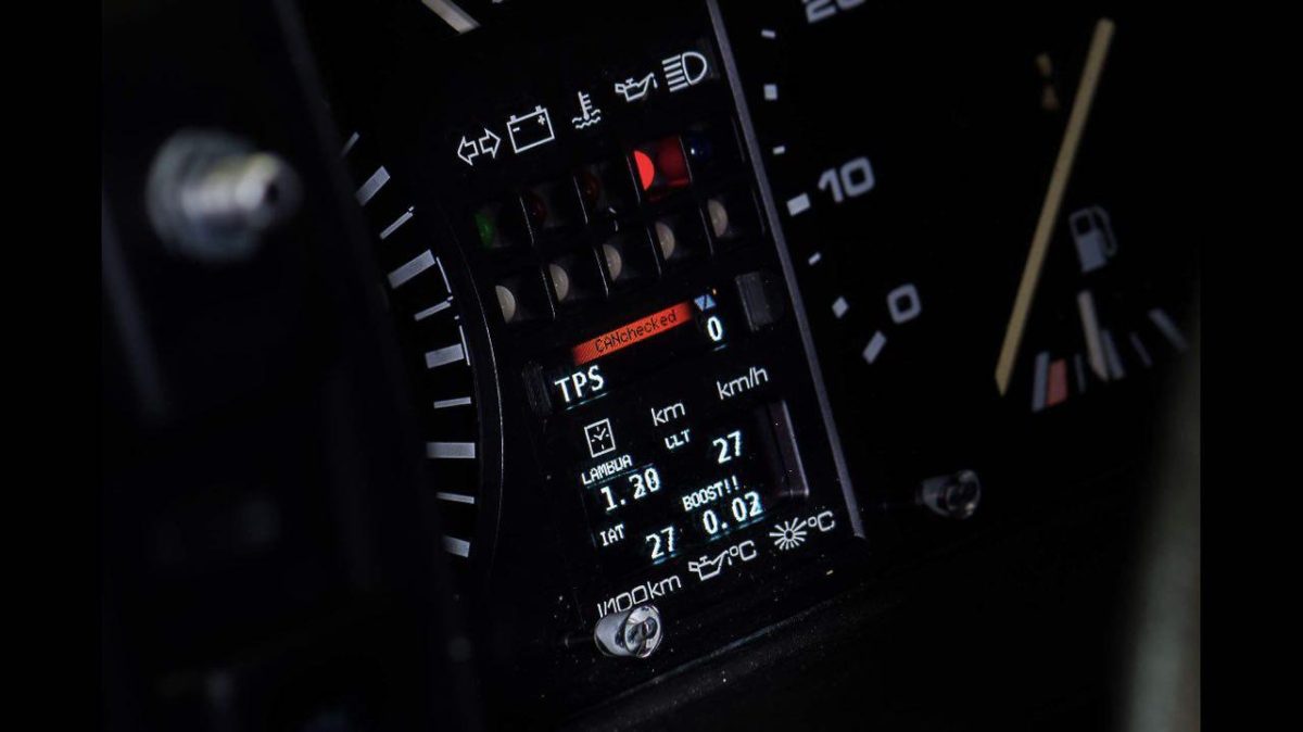
There is always a desire on the part of customers to influence the values in the control unit. Be it launch control, flat shift, a different boost pressure map or maybe just turning on the fan. There are many ideas. Now you can place a separate switch in the cockpit for each function or alternatively an intelligent display that supports “Can Bus Switching”.
– Can bus switching? –
Modern control devices communicate with their environment via Can Bus. A very stable two-wire communication medium that is popular not only in the automotive sector but also in industry. The control devices send data to surrounding systems such as ABS, speedometer, all-wheel drive so that the data can be used there accordingly. But communication with the control unit is also possible. More and more “aftermarket” control devices support the function. The control unit receives data via the Can Bus and can use this to (temporarily) change certain parameters.
– How do we do it? CANchecked implementation –
Due to the touchscreen of our MFD28 / MFD32 / MFD32S and the individually configurable view of the display, we are able to react very quickly to such requirements.
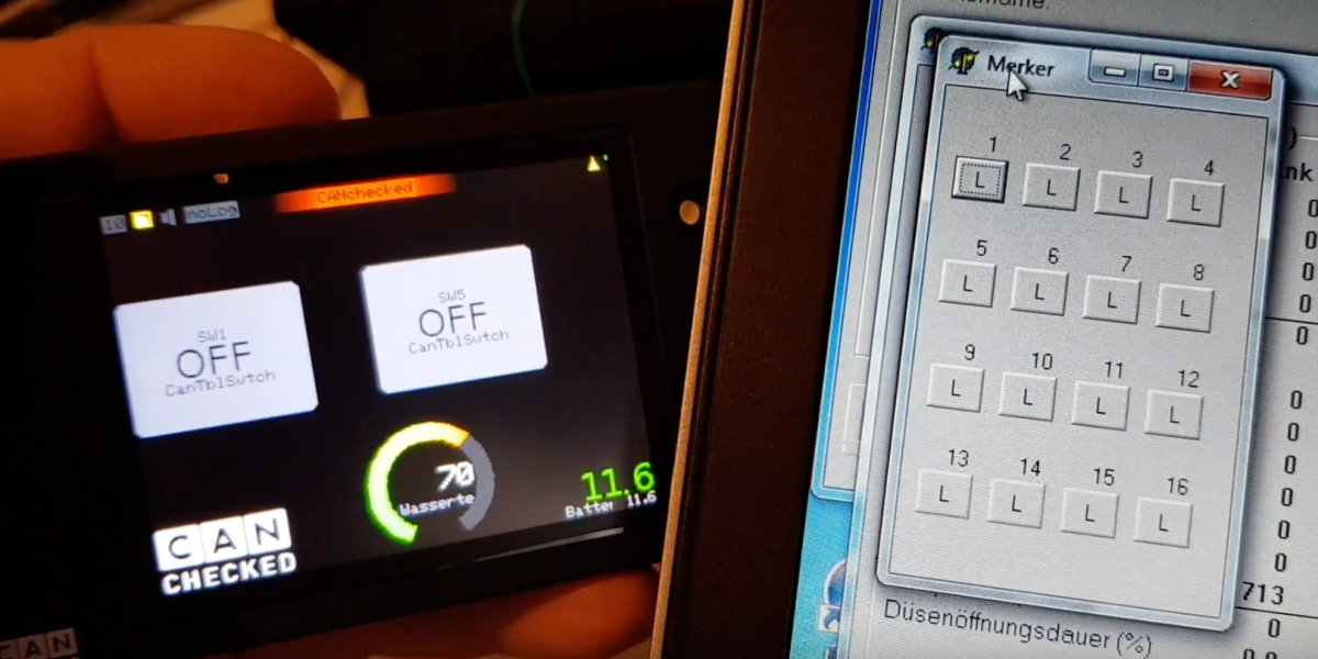
You can put a widget on the screen and change the widget type to “CANSwitch”. Now you have the possibility to choose between EIGHT different switches. You then have to store this in your control unit with the desired function, done. The communication takes over completely the display. No additional external switches or buttons are required. During operation, you can now tap the widget directly and thus trigger “Can Bus Switching”.
This feature can be used completely free of charge from display version v2.3
– Video –
We have created a video using a trijekt Bee as an example. The buttons on the display can of course be changed in size and position.
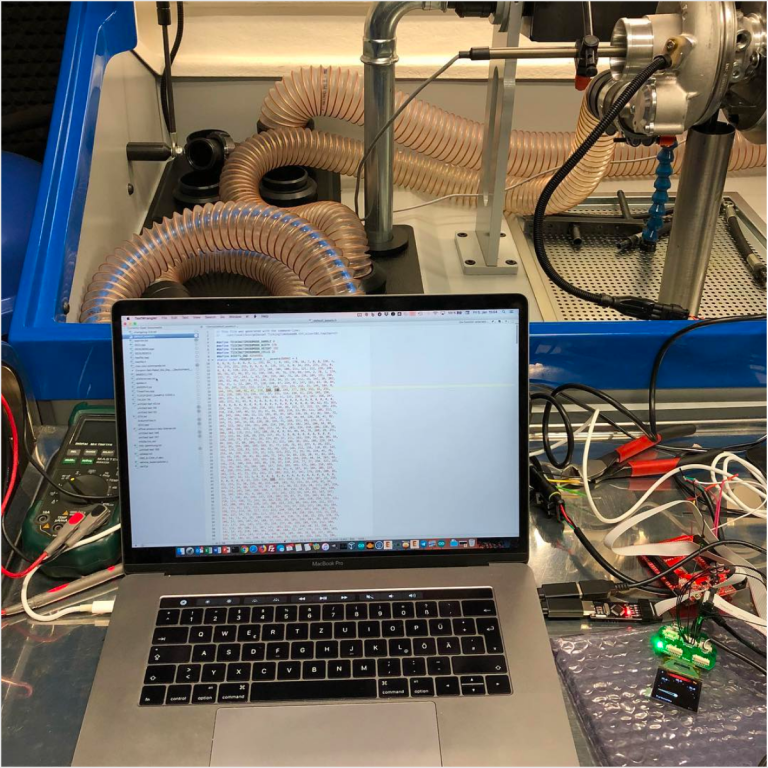
We had the opportunity to use the turbocharger test bench at the Turbo Center to advance the development of the turbo speed display.
Development Turbo Speed Gauge Gauge EFR Garrett
No additional electronics are used. The connection is made directly to the sensor from the turbocharger. This option will find its way into our MFD28 and MFD15 .
Details:
Direct connection to the display
Entry of a maximum value for warning (optical/acoustic)
different representations
The value shown must be multiplied by 1000 (e.g.: 27.1 results in an effective charger speed of 27100 rpm)
Configuration of the buckets in the loader directly on the display
Support for 5V sensors (please note when selecting sensors)
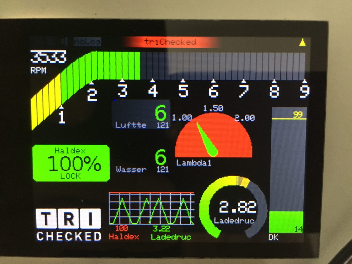
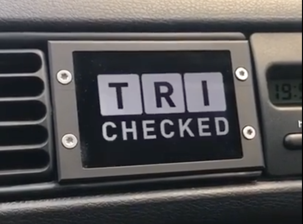
The extensive test of the Haldex control via the 2.8″ display took place on Lukas’ Golf 2 16V Turbo , including at the GLP in Ransel.
The aim was to control the Haldex directly via the Can Bus from the display, as all the relevant information for all-wheel drive operation is available here. Different modes can be selected (OFF, IDLE, LOCK, STREET – more on this later). This means the Haldex unit does not need to be converted. Only the six cables have to be routed to the rear.
The all-wheel drive can be quickly switched on via the touchscreen at the push of a button.
Existing 2.8″ displays can be retrofitted using a license.
So no additional display is needed and of course no further control. The 2.8″ display takes care of everything .
– Widget display in the display –
The customer with the Haldex license can add a new widget to the display, which can be used to control the Haldex and also shows the current blocking level of the Haldex. The widget, like all the others, can be freely determined in size and position.
-Advantages –
No conversion of the Haldex unit
No additional display required
Display of the current blocking level of the Haldex
Quick activation/deactivation of the all-wheel drive via touchscreen
Read errors directly on the display
Protective functions such as increased transmission oil temperature are still active
– Haldex control test – – Video –
– Vehicle details –
Vehicle:
Golf 2
Engine:
2L 16V Turbo
Drive:
Audi TT 4motion drivetrain with CANchecked control
A customer sent us this video, which demonstrates how to browse through the views.
Simply touch your finger twice in the left or right area and the next view will appear. The first press of the finger stops the display and the second press continues to scroll.
All TEN views can be designed individually. All widgets are customizable in size, type, color and position.
Here you can find more information about our 2.8″ display
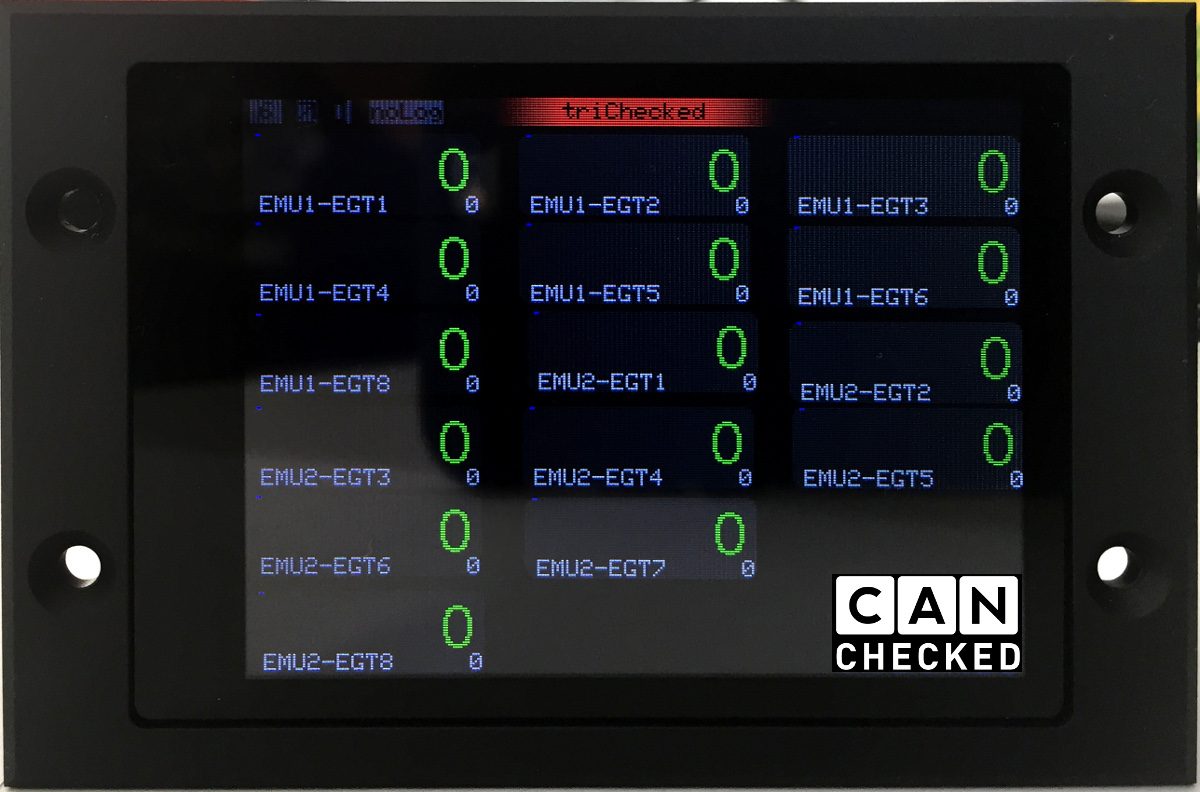
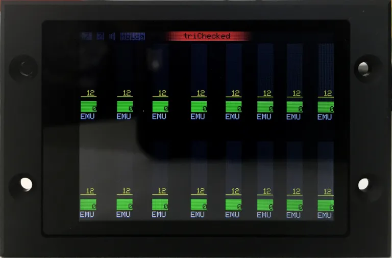
Something like this is also possible: 16x Type-K display. Due to the individual configuration of the MFD28, any CAN bus extensions can be connected. Here in the example 2x 8-fold AGT sensor boxes. Each box transmits its data directly to the display via CAN bus, where it is then shown and individual warnings can be given for each sensor. So that makes a total of 16 Type-K sensors that the customer can connect.
There are a wide variety of sensors available as Type-K. From 1mm for water/oil to 3mm for exhaust gas temperature up to 5mm. The thicker the sensor, the more resistant it is to high temperatures and vibrations, but the larger the diameter, the more sluggish it becomes.
The purpose mentioned was the water-flooded valve seat rings on an Audi S2 that had been extremely overloaded. This means you can quickly identify deviations among the individual cylinders and then react directly by tuning them. This also helps extremely with troubleshooting. You know immediately if a cylinder is not burning correctly.
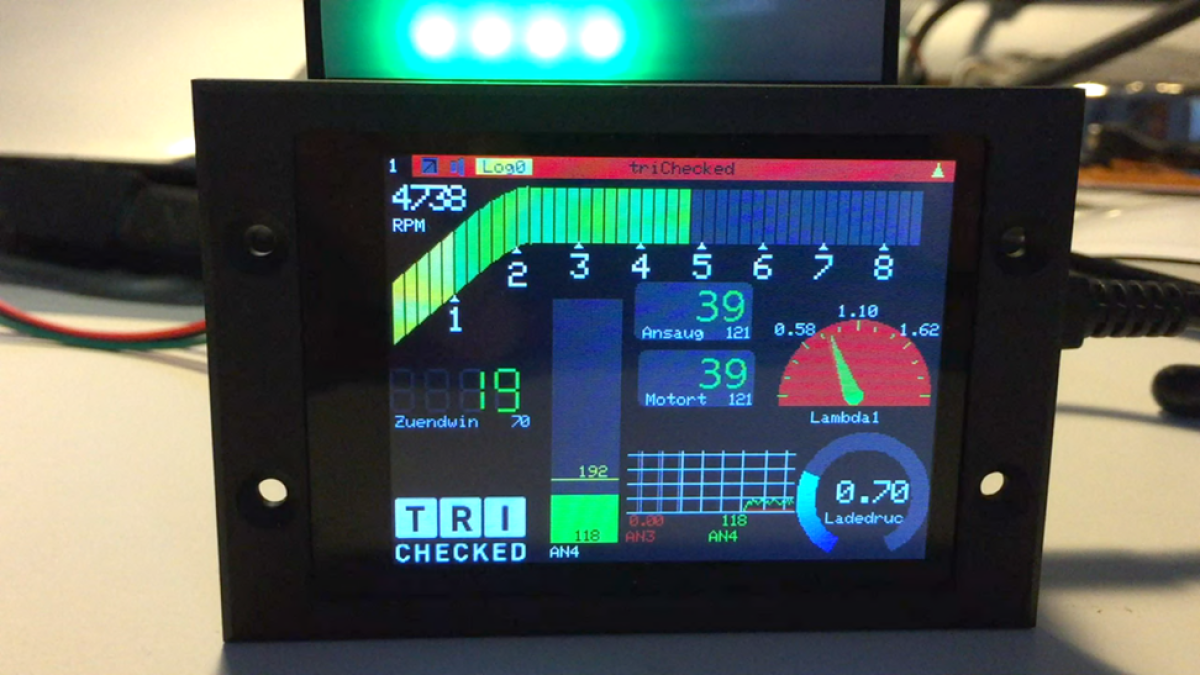
A small demo video showing what is possible with the display. It goes through three views, which show a wide variety of widgets and their sensors. The customer can create the views himself directly on the display with the touchscreen and the intuitive operation.
You can also see the shift light above the display. This is connected to the display via a 50 cm long cable and can therefore be flexibly accommodated in the vehicle interior. The settings for each LED can be made via the display. Not only speed limit per LED but also color can be freely determined. You can also set the brightness of the shift light.